[31호]고전류용 스텝모터 드라이버 모듈(AMIS-30543) 출시
Posted by 디바이스마트 매거진 on Wednesday, July 15, 2015 · Leave a Comment
고전류용 스텝모터 드라이버 모듈(AMIS-30543) 출시
Pololu는 최근 ON Semiconductor의 AMIS-30543 마이크로 스테핑 모터 드라이버 모듈을 출시했다. 이 제품은, Pololu에서 나온 다른 많은 스테핑 모터 드라이버에는 없는 진보된 기술이 추가된 고성능 스테핑 모터 드라이버 제품이다.
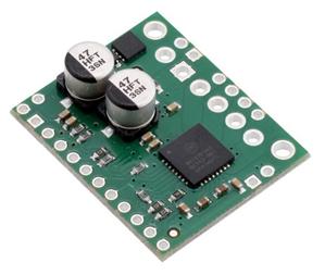
‘Pololu AMIS-30543 Stepper Motor Driver Carrier’ 제품은 브레드보드에 호환 가능한 2.56mm 핀 공간을 통해서 모든 중요한 기능을 확보했다. 터미널 블럭을 통한 전원이나 모터와의 연결 및 마운팅 홀을 통한 더 강력한 설정을 할 수 있게 된 것이다. 또한 reverse protection 등 중요한 기능을 모두 보유했다.
AMIS-30543는 최대 30V, 3A까지 가능하지만, 이는 다른 스테핑 모터 드라이버들의 경우와 같이, 뛰어난 냉각 상태를 가정한 이론적인 최대치이다. 방열판이 없는 상태의 상온에서 사용하는 경우, pololu의 다른 어떤 스테핑 모터 드라이버들보다 코일 당 약 1.8A 정도 더 나은 수치를 보인다. 제품의 SPI interface는 많은 고급 기능을 제공한다 : stepping 단계 설정 기능(최저 1/128 step 까지), 최대 전류 허용치 설정 기능, 전압 기울기 선택 기능, 방향 변경 기능, 출력 정지 또는 슬립 상태로 설정, 포지션 및 에러 모니터링 기능 등. 하지만 명심해야 할 점은, SPI를 통해서 모터의 step을 조절할 수는 없다는 것이다.
많은 사용자들은 실제로 ‘전원’을 관리하는 것보다 실제 활용에 있어서 더욱 편리한 “소프트웨어를 통한 전류 제한 설정” 기능의 탑재를 요청해 왔다. 스테핑 모터는 높은 토크가 필요하지 않은 정지 상태에서도 최대 전류를 사용하기 때문에 전원을 낭비하게 되고, 모터와 드라이버에 원치 않는 열을 발생하게 된다. 그리하여 예를 들면 3D 프린터의 경우에는 높은 토크가 필요하지 않기 때문에, 일시 정지 상태에서는 허용 전류치를 낮추는 것이 더 나을 것이지만, 다른 활용에 있어서 가속을 하는 경우나 순간적이고 즉각적으로 높은 스피드가 필요한 경우에는, 그 수치를 최대치로 올리고 싶을 것이다.
AMIS-30543의 SPI interface를 통한 허용 전류 설정 기능은, 코드를 통해서 이 모든 것을 가능하게 해 준다. 또 다른 고급 기능은 SLA (speed and load angle) output 이라는 기능으로, 모터의 back-EMF 전압의 기울기를 표시해 주는 기능이다. 이 신호는 토크와 속도에 대한 stall detection 또는 closed-loop control에 사용 가능한 아날로그 신호로 나타낸다.
Pololu의 Arduino library on GitHub(https://github.com/pololu/amis-30543-arduino)를 통해서 쉽게 활용이 가능하며, 드라이버를 구동하고, 설정하기 위한 기본적인 기능을 제공하며, 뿐만 아니라 고급 기능까지 접근할 수 있다.
| AMIS-30543 Stepper Motor Driver Carrier |
|

|
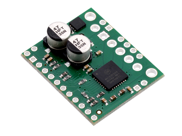
- This is a breakout board for ON Semiconductor’s AMIS-30543 microstepping bipolar stepper motor driver, which features SPI-adjustable current limiting, 11 step modes (from full-step through 1/128-step), back-EMF feedback that can be used for stall detection or optional closed-loop control, and over-current and over-temperature protection. The board operates from 6 V to 30 V and can deliver up to approximately 1.8 A per phase without a heat sink or forced air flow (it is rated for 3 A per coil with sufficient additional cooling).
|
|

|
Overview |
|
|
|
This product is a carrier board or breakout board for ON Semiconductor’s AMIS-30543 Micro-Stepping Motor Driver; we therefore recommend careful reading of the AMIS-30543 datasheet (495k pdf) before using this product. This stepper motor driver lets you control one bipolar stepper motor at up to 3 A output current per coil (see the Power Dissipation Considerations section below for more information). Here are some of the board’s key features:
- Standard step and direction control interface
- SPI interface for configuring settings (e.g. step mode, current limit, sleep) and reading status registers
- Speed and load angle output that can be used for stall detection or closed-loop control of the torque and speed based on the load angle
- Eleven different step modes: full-step (uncompensated, compensated 1-phase, or compensated 2-phase), half-step (uncompensated or compensated), 1/4-step, 1/8-step, 1/16-step, 1/32-step, 1/64-step, and 1/128-step
- SPI-programmable current control (from 132 mA to 3 A) enables your microcontroller to adjust the peak-current limit on the fly as more or less torque or speed is needed
- Intelligent chopping control that automatically selects the correct current decay mode (fast decay or slow decay)
- Low-EMI PWM with SPI-selectable voltage slopes
- Compatible with 5 V and 3.3 V microcontrollers
- Integrated 5V regulator that can be used to supply an external microcontroller
- Integrated watchdog function
- Open coil detection
- Thermal warning indicates when the driver is close to the thermal shutdown temperature
- Over-current status and shutdown (short-to-ground and shorted-load protection)
- Reverse voltage protection
Note: This driver needs to be enabled and configured through its SPI interface on power up, so your microcontroller must be capable of acting as an SPI master (either with an SPI peripheral or software SPI).
|
|
|
Included hardware |
|
|
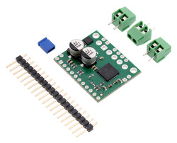 |
This product ships with all surface-mount components—including the AMIS-30543 driver IC—installed as shown in the product picture. However, soldering is required for assembly of the included through-hole parts. The following through-hole parts are included:
- One 1×20-pin breakaway 0.1″ male header
- Three 2-pin, 3.5 mm terminal blocks (for board power and motor outputs)
- One 0.1″ shorting block (for connecting IOREF to neighboring VDD pin)
The 0.1″ male header can be broken or cut into smaller pieces as desired and soldered into the smaller through-holes. These headers are compatible with solderless breadboards, 0.1″ female connectors, and our premium and pre-crimped jumper wires. The terminal blocks can be soldered into the larger holes to allow for convenient temporary connections of unterminated power and stepper motor wires. You can also solder your motor leads and other connections directly to the board for the most compact installation. |
|
|
Specs |
|
|
|
|
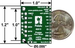
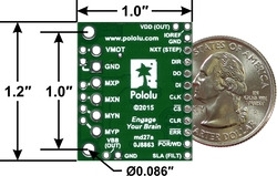
| Size: |
1.0″ × 1.2″ |
| Weight: |
4.0 g1 |
|
|
|
| Minimum operating voltage: |
6 V2 |
| Maximum operating voltage: |
30 V |
| Continuous current per phase: |
1.8 A3 |
| Maximum current per phase: |
3 A4 |
| Minimum logic voltage: |
2.5 V |
| Maximum logic voltage: |
5.5 V |
| Microstep resolutions: |
full, 1/2, 1/4, 1/8, 1/16, 1/32, 1/64, 1/128 |
| Reverse voltage protection?: |
Y |
|
|
Notes:
1Without included optional headers or terminal blocks.
2The regulated 5V (VDD) output current is reduced for input voltages under 8 V, and sleep mode is not available for input voltages under 9 V.
3Without a heat sink or forced air flow.
4With sufficient additional cooling. |
|
|
|
|
 |
|
제품 구매하러 가기